A Bi-Monthly Magazine
Borrowing From Yesterday To Do the Work Of Today
Offering Resources to Promote Self-Sufficient & Back-to-the-Land Living
Build a Better Baler
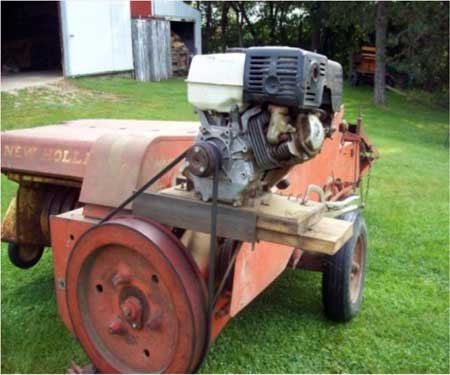
A fellow visitor on Rural Heritage's Front Porch posted this photo of a neighbor's engine mount in reply to Todd's query for examples of engine-driven balers.
Having made hay with my good friend, Tommy, on a number of occasions and been witness to the versatility of his engine-driven NH 68 baler, I decided I needed to modify my own NH 273 baler to function similarly. The first step, due to economics, was finding an engine the right size, at the right price. I believe Tommy’s Wisconsin engine is around 15 hp, so I felt I needed a little more than that since my baler is a bit larger than his.
For me, the going rate on new Honda engines was just impossible In my favor, I like to
peruse the classifieds and one lucky day ran across a 24 hp Honda engine advertised really
cheap. I went over to look at it and liked what I saw. Fella said it came off a Zero Turn
Mower. Somebody dropped it off where he worked for some minor repair and never came back
for it. Says he bought it for the repair cost and after I talked him down a little, my
$75 engine was on its way home. Almost forgot, he came down because it wouldn’t run unless
you were pouring fuel directly into the carburetor. It turned out to be a frozen fuel
shutoff solenoid.
Now that I had my engine, I could begin measuring and designing an engine mount. I first
had to seek advice from the folks on The Porch to see if anyone had already done this and
had any shortcuts. To my surprise there wasn’t any firsthand knowledge. Plenty had seen
them but never done it themselves. Alas, a fellow Porch Participant emailed me several
photos of, I believe, his neighbor’s Honda powered baler. The design was very primitive,
but the concept was amazingly simple. The motor was attached to a board and was slid out
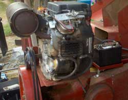
Armed with what I had seen on Tommy’s baler and with the simple design from Jerry’s photos, I was ready. The first thing to consider was the direction of the engine’s counterclockwise rotation, which means the front of the motor will need to point to the rear. Next on the design consideration was which side to mount it on. I wanted it on the pickup side, but the engine’s oil cooler would be up against the Plunger Arm Cover and not get enough air flow. With that out of the way, I noticed the baler had a lot of original holes in its frame. No need to drill new ones if you can utilize the existing ones. I used a piece of cardboard, holding it up to the baler, cut and shaped it into a useable pattern. I picked through my pile of scrap metal for a flat plate and a few pieces of angle iron to make the motor mount. Clamped the prototype to the baler and drilled through the existing holes. With my mount installed, I aligned the motor so as to give plenty of clearance for the baler’s plunger arm cover to operate properly and aligned the end of the motor’s crankshaft with the baler’s flywheel. I marked and drilled the mounting holes for the motor. I had some rubber vibration dampeners from another engine project and installed those between the engine block and the mounting plate.
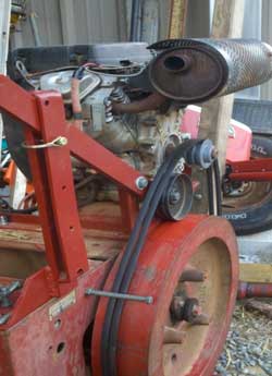
A quick trip to the nearest industrial/mechanical parts store got me a double V-belt pulley for the crank and a pair of 83-inch belts for around $45. After installing those around the baler and motor, it was time for some head scratching on how to engage and disengage the motor. The original NH’s used a lever with an idler pulley, so that would be a logical choice for me as well. After looking at it a couple of different ways, I settled on just welding an upright piece of angle to the motor mount and bolting to that a piece of flat bar with an idler pulley on the end of it. Quick trip to the mower store, and I had an idler pulley for $15. I made a simple bracket for the handle to slide through with a few strategically placed holes for a linchpin to hold the pulley in and out of contact with the drive belts. Next, I made a simple angle iron battery bracket which required drilling two holes into the baler’s frame.
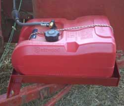
Wanting to keep a clear view of the bales coming out the bale chute and taking in the fact my motor has a fuel pump, I wanted to stow the fuel tank on the rear of the baler out of the operator’s line of sight. Luckily for me, my baler had a perfect spot just below and in front of the twine box. I made a simple angle iron frame, drilled three more holes and bolted it to the baler’s frame supports. Next came the fuel line. Not being thrilled about a rubber line getting pinched or cut, I made yet another trip to the store. This time to the auto parts store, where I bought a new lawnmower battery and 10 feet of 1/4-inch flexible steel tubing at a cost of $55. I ran the tubing between the drive chains and baler frame, turned 90 degrees and went between the sheet metal and the knotters. Attaching a short piece of rubber line at the motor end and a marinetype squeeze primer at the other, my baler project was complete.
The total time I spent was probably two weeks, but could be done easily in a day now that
I’ve done it. There was a lot of pondering and even a trial run before I settled all my questions.
The engine’s 24 hp is a little oversized, but better to have too much than not enough. During our
trial run, it ran about half throttle while baling an average size windrow of Pearl Millet. It
ran so quietly, in fact, I was hearing a lot of new noises out of the baler. After quite a bit
of searching, I found most of the issues and have rectified them and am glad I did before things
became irreparable.
It has been a very rewarding project. The baler operates, I feel, even better than it did as a
PTO drive. Now I’m waiting anxiously for the grass to grow some more so I can get out my shiny
new toy.